Online Emi Filter Design Tool

ADVERTISEMENT
Meeting EMI standards is a one of the biggest challenges for power system designers, with passive filters being a key weapon to attenuate unwanted frequencies in DC-DC converters. Designing filters, however, requires complex and time-consuming calculations, unless you use the Power Bench Filter Design Tool.
The Filter Design Tool makes the design of filters to eliminate EMI easy. All you need to do is select the frequency you need to suppress, and the amount of attenuation you require, and the tool does the rest.
How to Input Your Filter Requirements
When you open the Filter Design Tool, you are presented with a form with four inputs:
- The amount of attenuation required
- The frequency that needs to be attenuated
- The topology of the filter
- A selector to identify whether the converter is regulated or unregulated
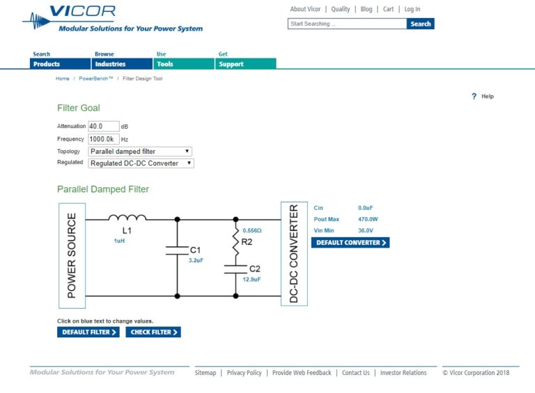
Fig-1-Filter-Design-Tool-768×565 Let's assume we are designing a DC-DC input filter for a regulated power component and have done some testing that shows noise at 50kHz needs to be attenuated by 20dB.
This isn't particularly demanding, so let's just put the values in and click the "DEFAULT FILTER" button, which will create the filter for us. We're presented with the following solution:
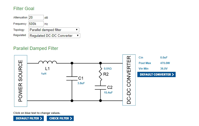 The tool also gives us the opportunity to analyze the performance of the filter, so we'll click "CHECK FILTER" to get a graph showing the attenuation by frequency.
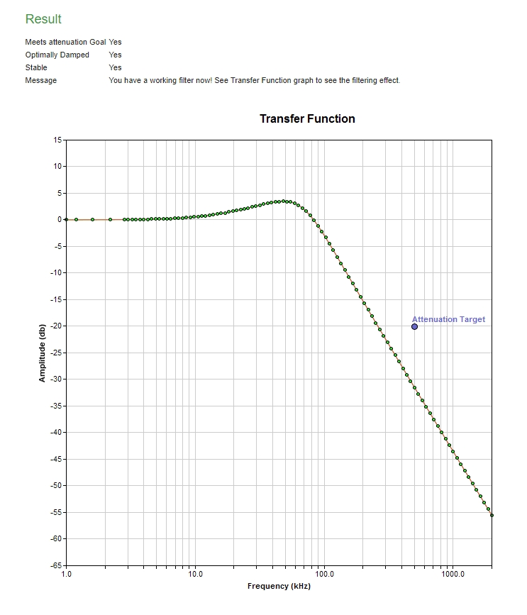 The tool checks to see whether the filter meets the attenuation goal that was set, if it is optimally damped and ensures it will also be stable. In our example the filter meets all three of these criteria.
The attenuation can also be analyzed using the graph, which shows we are well below the target attenuation at 50kHz. The graph also shows the resonance at about 40kHz: obviously if there was any noise at this frequency, it would be slightly increased on the output.
Real-World Components and Tolerances
The filter that the tool designs includes some non-standard components. 3.8µF and 15.4µF are not standard values of capacitance, so let's assume we use standard 3.3µF and a 15µF instead. We will also have to use an 0.5Ω resistor. These changes in values will impact the performance of the filter, but all we need to do is to click on the values and change them manually. Once we update these values, we can see that the filter still meets our requirements and if we want, we could check the attenuation graph with these new values.
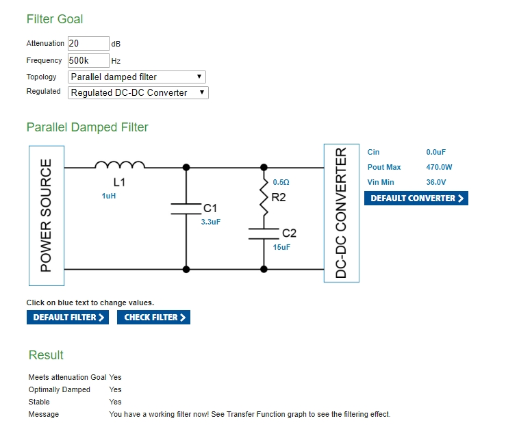
Fig-4-Real-World-Values This approach can be used to analyze the impact of component tolerances.
Selecting a DC-DC Converter
The filters we have designed so far have been for an ideal converter with no input capacitance. Let's now assume we are designing for a the 28V input, 15V output DCM (DCM3623T50M17C2T70).
If we click on the values for the converter on the right-hand side, we can change them to match the values from the DCM data sheet:

Fig-5-Input-values-for-DCM If we change to these values and then click "DEFAULT FILTER", we will see that the values for the filter are now very different to take into account the DCM's parameters.
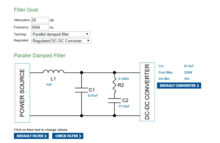
Fig-6-Filter-with-values-for-DCM Selecting Different Topologies
The filter design tool will create filters using five different topologies:
- Parallel damped filter
- Series damped filter
- Simplified series damped filter
- Two-stage filter
- Simplified two-stage filter
Each topology offers its own benefits and limitations.
Parallel Damped Filter
A parallel damped filter is basically a simple two-stage LC filter (L1 and C1), with a damping resistor, R2. As with any other second-order filter, ideally it provides 12dB per octave of attenuation after the cutoff frequency.
The damping resistor has been introduced to reduce resonance at the cutoff frequency. The capacitor C2 blocks DC, but should have an impedance that is much lower than that of R2 at the cutoff frequency.
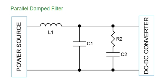
Fig-7-Parallel-Damped-Filter Series damped filter
A series damped filter uses the same LC filtering elements to create a second order filter, but places the damping across the inductor. At the cutoff frequency it's important the impedance of L2 is less than that of the damping resistor, R2.
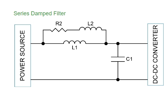
Fig-8-Series-Damped-Filter The filter tool also offers a simplified series topology, which eliminates L2, reducing size and cost of the filter, although this results in less effective damping at the cutoff frequency.
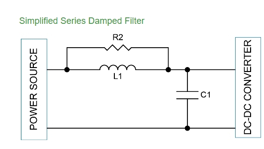
Fig-9-Simplified-Series-Damped-Filter Two-Stage Filters
A two-stage filter uses two inductors and two capacitors for filtering, providing a fourth-order solution that ideally provides 24dB per octave of attenuation. Although the two-stage filter introduces more filtering components, it is often cheaper and smaller than an LC filter because it allows the use of smaller value inductors and capacitors.
There are two options for the two-stage filter: a series damped topology and a simplified series damped topology.
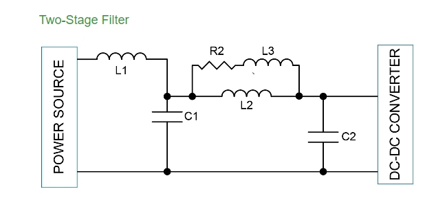
Fig-10-Two-stage-filter Two stage filters can be unstable, so it is important to ensure that the design will be stable across the range of component tolerances.
Conclusion: Fast Filter Design
Input filters are important to ensure compliance with EMI regulations, but they can be complex to design by hand. The Vicor Filter Design Tool, however, allows filters to be quickly architected and analyzed to greatly increase the likelihood of systems passing EMI testing first time.
Online Emi Filter Design Tool
Source: https://electronicsmaker.com/the-quick-and-easy-way-to-design-emi-filters-online
Posted by: duckwifeentent1998.blogspot.com

0 Response to "Online Emi Filter Design Tool"
Post a Comment